GFCI Outlet Testers Explained: What the Wiring Fault Codes Actually Mean and Which Tester Shows Them Clearly
You plug a little device into a wall outlet, a few lights blink on — or don’t — and somehow that tells you whether the wiring behind the wall is safe. If that feels like reading tea leaves, you’re not alone. A GFCI outlet tester (also called a receptacle tester) is a simple plug-in tool that checks whether a standard 120 V outlet is wired correctly and whether the GFCI protection — the ground fault circuit interrupter, the device that cuts power within milliseconds if it detects a shock hazard — is actually working. Every residential kitchen, bathroom, garage, and outdoor outlet is required by the National Electrical Code to have GFCI protection, which makes these testers an everyday tool for electricians, home inspectors, and anyone who just bought a house with a questionable electrical panel. This guide breaks down exactly what those fault codes mean, where the three-LED models fall short, and which testers give you enough information to make a confident decision — without pulling wire until you know what you’re actually dealing with.
What the Fault Codes Actually Mean (and Why Three LEDs Aren’t Always Enough)
The classic three-LED tester has been around for decades. It works by comparing the voltage relationships between the hot, neutral, and ground conductors at the receptacle, then illuminating a specific combination of lights that maps to a fault condition. Most testers ship with a legend on the back. Here’s what the standard codes translate to in plain English:
| LED Pattern | Fault Condition | What It Means on the Job |
|---|---|---|
| All off | Open hot | No voltage reaching the outlet — dead circuit or tripped breaker |
| Two lit (varies by brand) | Open neutral | Hot and ground are live; neutral wire is broken or disconnected |
| One lit | Open ground | Hot and neutral are correct; ground wire missing or disconnected |
| Correct | All three wires properly connected | Outlet passes wiring check |
| Hot/neutral reversed | Hot and neutral swapped | A reversed connection that can still energize equipment chassis |
Open ground is the most common fault you’ll find in older homes — pre-1960s two-wire systems were never grounded to begin with, and three-prong outlets were added later without running a proper ground wire. Open neutral is the one that gets dangerous fast: the outlet may still power devices (hot and ground are present), but without neutral, voltage can float unpredictably and equipment can be damaged. Hot/neutral reversed often passes a visual inspection because the outlet functions normally — but the neutral screw is energized, which means touching the neutral terminal during a repair can deliver a shock even with the device switched off.
The limitation with three-LED testers is exactly what you’d expect: three LEDs give you seven possible states (2³ = 8, minus the all-off “no power” state), and that’s enough to catch the common faults but not enough to give you real diagnostic depth. They also can’t tell you the actual voltage at the outlet, and they can’t distinguish between a correctly wired outlet and some edge cases — including the notorious bootleg ground.
The Bootleg Ground Problem: What Standard Testers Miss
A bootleg ground — sometimes called a false ground or a jumpered ground — is exactly what it sounds like: someone has connected a wire from the hot or neutral terminal to the ground terminal to fool a three-LED tester into reading “correct wiring.” This was a common shortcut in older renovation work where adding a true equipment ground would have meant running new wire.
The critical problem: the tester shows green (or the “correct” pattern), but the ground is not connected to the earth ground at the panel. If a fault occurs inside a connected appliance, that fault current has nowhere safe to go — it goes through the person holding the appliance instead. Per the NFPA 70 (National Electrical Code) 2023 edition, Article 406, existing ungrounded outlets are permitted to be replaced with GFCI-protected outlets with a “No Equipment Ground” label, but they may not be replaced with a grounded receptacle unless a true equipment ground is available.
Can a standard plug-in tester detect a bootleg ground? The honest answer, addressed more fully in the FAQ below, is that most cannot — and this is a genuine limitation worth knowing before you rely on a tester as your final word on outlet safety.
Three-LED vs. LCD Display Testers: Where the Klein RT250 Changes the Workflow
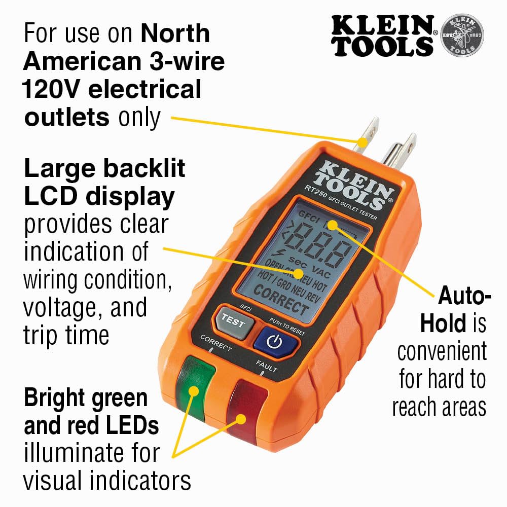
This is where the format of your tester starts mattering to actual job efficiency. Reviewers of the Klein RT250 consistently highlight one specific upgrade over traditional LED models: the backlit LCD display that shows live voltage alongside the wiring condition simultaneously. Owners describe this as removing guesswork from outlet installation in a way that a three-LED pattern simply can’t match.
Here’s the practical difference. With a three-LED tester, you see “open ground” — but you don’t know whether you’re looking at 118 V or 104 V. Voltage drop matters. An outlet showing correct wiring at 102 V on a 20-amp circuit serving a refrigerator compressor is a conversation you need to have with whoever manages that building. A three-LED tester doesn’t start that conversation.
The RT250’s display reads actual voltage, which gives you:
- Confirmation that the outlet is within normal range (nominally 120 V, acceptable range typically 114–126 V per ANSI C84.1)
- A second data point to distinguish a weak connection from a correctly wired outlet — a loose neutral can show “correct” pattern at degraded voltage before it fails completely
- Faster documentation for inspection reports
One RT250 reviewer specifically describes using the tester to trip a GFCI and then trace which downstream outlets lose power — a workflow that deserves its own walkthrough.
Step-by-Step: Using a GFCI Tester to Map Downstream Outlets
This is one of the most useful things an outlet tester can do on a real job, and most people don’t use it systematically. Here’s the workflow:
-
Plug the tester into the GFCI outlet (the one with TEST and RESET buttons) that you want to map. Confirm it shows correct wiring and live voltage.
-
Press the TEST button on the tester (not on the outlet itself). The tester sends a controlled ground fault current — typically 6 mA, just above the 4–6 mA GFCI trip threshold per UL 943 — and the GFCI should cut power within 1/40 of a second.
-
Confirm the outlet is dead — the tester display goes blank or LEDs go out.
-
Walk to every other outlet in the area — especially in adjacent bathrooms, the garage, exterior outlets, and the kitchen counter circuit — and plug in the tester. Any outlet that is also dead is downstream of the GFCI you just tripped. Note those locations.
-
Return to the GFCI outlet and press RESET. Confirm power is restored to all downstream outlets.
-
Label your findings. In a home with an unlabeled panel, this process — combined with a breaker finder — builds an actual circuit map in under an hour.
One practical note from RT250 owners: the tester can be snug to remove from some outlets, particularly spec-grade receptacles with higher contact tension. The fix is simple — grip the tester body firmly rather than pulling by the bottom edge, and use a slight rocking motion. Don’t lever against the outlet faceplate.
Kit vs. Individual Purchase: The Klein 80101 and 80025
For anyone mapping an unlabeled panel from scratch, the combination of a GFCI tester and a breaker finder is genuinely more useful than either tool alone. The Klein 80101 kit pairs a GFCI outlet tester with a breaker finder, and reviewers consistently frame this combination as a “new homeowner survival kit” — specifically in the context of homes where the panel labels are missing, wrong, or written in handwriting no one can read anymore. The workflow is straightforward: the GFCI tester confirms which outlets are live and correctly wired, the breaker finder identifies which breaker controls each circuit, and you end up with a labeled panel in a single afternoon.
The Klein 80025 two-piece kit draws similar praise for build quality in aggregated reviews, with one consistent note: owners wish it came with a carrying case when comparing it to individual purchases that can be stored in a dedicated tool bag pocket. If you’re buying for a service van where organization matters, that’s worth factoring in — a simple zippered pouch solves it, but it’s an extra step.
By the numbers:
- GFCI trip threshold per UL 943: 4–6 mA (Class A devices)
- NEC 2023 Article 210.8: GFCI protection required in bathrooms, kitchens, garages, outdoors, crawl spaces, unfinished basements, and boathouses
- Acceptable voltage range (ANSI C84.1): 114–126 V at the utilization point
- Standard receptacle tester fault states detectable by LED pattern: 7
Frequently Asked Questions
What does “open ground” mean on my outlet tester and is it dangerous?
Open ground means the ground wire at that outlet is either missing, disconnected, or never installed. The outlet will still power devices normally — hot and neutral are complete — but there’s no safe path for fault current if something goes wrong inside a connected appliance. Per EC&M’s guidance on receptacle wiring faults, open ground is extremely common in pre-1960s wiring and is a code violation in new work. It’s not an immediate electrocution hazard the way open neutral is, but it’s not acceptable to leave it in any circuit serving modern appliances or electronics.
Can a GFCI outlet tester detect a bootleg ground?
Standard three-LED testers generally cannot. A bootleg ground — where the ground terminal is jumped to neutral at the outlet — presents the same voltage relationships as a correctly wired outlet, so the tester reads “correct.” Some advanced testers with impedance measurement capability can detect the difference, and a good clamp meter or a full multimeter measurement between ground and neutral (looking for a voltage differential under load) will expose it. If you’re in older work and the “correct” reading doesn’t match the condition of the rest of the wiring, don’t trust the tester alone.
Why does tripping a GFCI outlet also kill power to another outlet in a different room?
Because GFCI protection can be wired to cover multiple outlets downstream on the same circuit — the GFCI outlet or breaker is protecting everything fed from its load terminals. This is actually code-compliant and common. The GFCI at the first outlet in the chain protects all subsequent outlets, which is why one bathroom GFCI might also control a garage outlet or a hallway outlet. Use the step-by-step tracing workflow above to map exactly which outlets are downstream.
My tester shows correct wiring but the outlet feels warm — what should I check next?
A warm outlet is a mechanical problem, not a wiring-polarity problem — which is why the tester shows correct. Common causes: loose wire connections creating resistance at the terminal (resistance generates heat under load), a receptacle with worn contacts that creates a poor connection, or a device plugged in that’s drawing near the outlet’s rated ampacity continuously. Fluke’s application notes on ground fault interrupters note that thermal issues at receptacles are often connection-quality problems rather than GFCI-related. The next step is to de-energize the circuit, pull the outlet, and inspect the terminations — look for discoloration, melted insulation, or loose backstab connections. Replace the outlet and use screw terminals.
Can I use a standard outlet tester on a 20-amp T-slot receptacle?
Yes — standard outlet testers fit 20-amp T-slot receptacles because the T-slot accepts both 15-amp and 20-amp plug configurations. The tester’s ground and neutral prongs seat normally; only the hot prong changes shape between 15A and 20A devices, and the T-slot accommodates both. You’ll get a valid wiring-condition reading either way.
What does the voltage readout on the Klein RT250 tell me that the lights alone cannot?
The LED pattern tells you the topology — which conductors are present and correctly positioned. The voltage number tells you the quality of those connections under light load. An outlet showing “correct” at 108 V on a 120 V circuit has a resistance problem somewhere upstream — a loose connection, an overloaded circuit, or significant voltage drop over a long run. That’s actionable information that a three-LED tester simply doesn’t surface. On commercial work where you’re documenting outlet condition for a facilities manager or an inspection report, having a voltage number to record is the difference between “passed visual inspection” and actual measured data.