A digital multimeter (DMM) — the handheld instrument most people picture when they think “electrical tester” — measures voltage, current, and resistance by reading a signal and displaying a number. That’s its whole job, and it does it exceptionally well. A power probe, sometimes called an automotive circuit tester or circuit probe, does something fundamentally different: it feeds power into a circuit or commands a component to fire, all while simultaneously telling you what’s happening electrically. If you’ve ever tried to diagnose a dead fuel injector or a sticky solenoid using nothing but a multimeter, you already know the gap. This article breaks down exactly where the two tools diverge, which use cases genuinely require a power probe, and how to think about building a combined kit that covers every diagnostic scenario you’ll encounter on a modern vehicle.
What a Power Probe Actually Does (That Your DMM Cannot)
A multimeter is a passive measurement device. You connect its leads, it reads whatever the circuit is doing right now, and it reports back. That’s fine for checking whether 12 V is present at a fuse, measuring resistance on a sensor, or confirming continuity in a wire. But automotive diagnosis frequently demands something more: you need to apply power or ground to a component deliberately, independent of the vehicle’s own switching logic, to see whether that component works at all.
Consider a fuel injector. With a DMM, you can measure the coil resistance — typically 12–16 Ω on a high-impedance injector — and confirm the winding isn’t open or shorted. That takes about 20 seconds. What it cannot tell you is whether the injector actually opens and sprays when commanded. The coil can test perfect on resistance while the pintle is stuck from varnish. A power probe lets you pulse 12 V directly to the injector harness connector, bypassing the ECU entirely, so you can hear the injector click or watch a noid light flash in real time. That is a capability difference, not a marketing distinction.
The same logic applies to relays, solenoids, cooling fans, window motors, and any actuator that needs to move. A DMM measures the electrical potential for movement; a power probe proves actual function.
According to the Test Equipment Depot Digital Multimeter Buyer’s Guide, multimeters are purpose-built for passive measurement tasks — resistance, continuity, AC/DC voltage, and current — but the guide explicitly notes that active circuit stimulation falls outside a DMM’s design intent. That framing clarifies why the two tools occupy different positions in a diagnostic kit rather than competing for the same slot.
Back-Probing, Wire Piercing, and Why the Distinction Matters
Here’s a technique question that trips up many intermediate-level technicians: when you need to measure voltage inside a sealed automotive connector while it’s still plugged in, how do you get your meter leads in there?
The instinct is to push a sharp probe tip through the wire insulation — a technique called wire piercing. It works, technically. The problem is what it leaves behind. Automotive wiring is routed through areas with constant vibration, moisture, and temperature cycling. A puncture in the insulation, even a tiny one, becomes a path for corrosion to wick into the copper strands. Electronic Design’s coverage of automotive electrical diagnostics identifies pierced test points as a recurring source of intermittent codes, particularly on CAN bus and sensor signal wires where corrosion changes the wire’s resistance and distorts the signal long after the original diagnostic session.
Back-probing is the correct technique. It means inserting a thin probe tip into the back of the connector — the wire side — alongside the terminal, without breaking the insulation. This requires a probe tip slim enough to slide past a Weather Pack or Deutsch connector seal, and the patience to work carefully.
You can back-probe with any DMM. The probe tips are the limiting factor, not the meter. But when you’re already using an automotive power probe with built-in power delivery, having compatible back-probe accessories means a single probe tip rides in one hand while you control power application with the other — faster workflow, fewer dropped leads under a dash.
Voltage Drop on Ground Connections: The Number That Tells the Story
Ask any experienced automotive electrician where the majority of intermittent electrical problems originate, and most will say the same thing: ground circuits. A ground connection that looks fine visually — no corrosion visible, wire seated in the terminal — can still carry enough resistance to cause havoc on sensitive electronics.
The measurement technique is straightforward but the interpretation requires calibration. You set your DMM to DC millivolts (mV) and measure across the suspect ground connection — one lead on the chassis ground stud, one on the component’s ground terminal — while the component is loaded and drawing current. What you’re measuring is the voltage drop caused by resistance in the connection.
ECM Web’s coverage of automotive ground circuit diagnosis establishes the industry threshold clearly: anything above 100 mV (0.1 V) under load indicates a problem connection. A reading of 50 mV or less is clean. Between 100 mV and 300 mV you’ll start seeing intermittent oddities — modules resetting, sensors reading erratically, warning lights coming and going. Above 300 mV you typically see hard faults. Fluke Corporation’s published application material on voltage drop measurement confirms the same principle applies broadly: resistance in a grounding path creates a voltage offset that downstream electronics interpret as a signal error rather than a power problem.
A standard DMM performs this measurement perfectly well. You don’t need a power probe for voltage drop testing. What you do need is the discipline to load the circuit properly — checking a ground with the component switched off is nearly worthless.
Choosing the Right Tool: Budget, Mid-Tier, and Premium Options
Not every technician needs the same kit. The three tiers below map to real differences in use frequency, component load requirements, and diagnostic depth — not just price preference.
Budget Tier: Entry-Level Probes and Basic Graphing DMMs
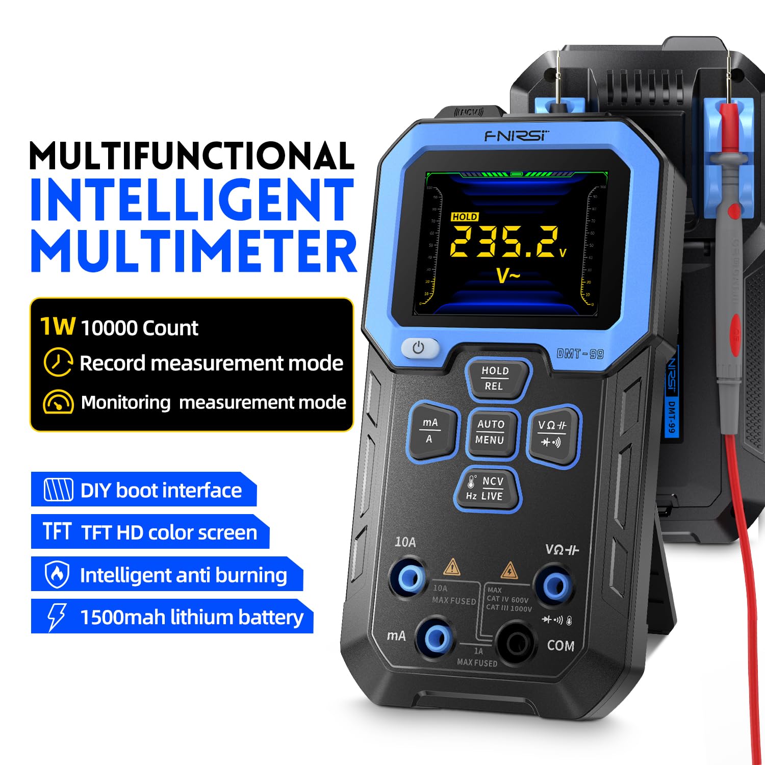
At the entry level, tools in the $40–$70 range handle the most common DIY tasks: confirming power at a test point, applying battery positive or negative to verify a relay or solenoid clicks, and basic voltage measurement during accessory installation. One example use case documented by buyers in this tier: hardwiring a dash cam with a fuse tap, where the probe confirms constant versus switched power and tests ground quality before the tap is committed.
A graphing DMM in this range — instruments that plot current on a timeline rather than displaying only a static number — adds genuine diagnostic capability for parasitic battery drain jobs. Instead of watching a frozen amperage reading, you watch the draw step down in real-time as modules go to sleep. Any module that wakes unexpectedly appears as a spike on the graph, giving you a timing signature to track. For a technician doing one parasitic drain diagnosis a month, this graph mode turns a 90-minute static-measurement session into a 20-minute observation.
The honest assessment: budget probes perform basic power application adequately. Wire gauge and connector quality are thinner, which matters for sustained loads but is acceptable for occasional DIY tasks.
FNIRSI
$35.99
In stock on Amazon
Check price on AmazonMid-Tier: The Autel PowerScan PS100 and Comparable Instruments
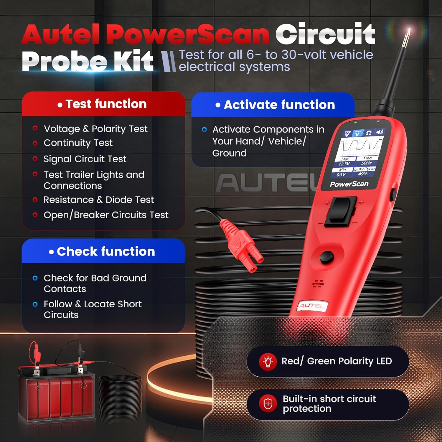
The Autel PowerScan PS100 sits in the $80–$110 range and represents the entry point for tools that hold up to regular professional use. Aggregated reviewer commentary consistently positions it as competitive with the category benchmark on features and favorable on current street price. The Autel includes a relay test function and an LED indicator array that reviewers describe as useful for quick-scan triage when you’re moving through a multi-circuit diagnosis rapidly.
For a mobile diagnostics operation or a technician who isn’t running a power probe all day every day but uses one several times a week, the mid-tier instruments represent the best value crossover: professional-grade function without the price premium of tools designed for sustained daily shop loads.
The Test Equipment Depot Digital Multimeter Buyer’s Guide notes that mid-range instruments in this class typically bridge the gap between consumer-grade durability and professional reliability, a description that fits the PS100’s positioning well.
Autel
$84.99
In stock on Amazon
Check price on AmazonPremium Tier: Power Probe III and Instruments with Waveform Capture
Power Probe (the brand) has been the category benchmark for automotive circuit probes for over two decades. The Power Probe III, at roughly $90–$110, delivers reliable power and ground application, an audible voltage indicator, and build quality that holds up to daily shop use. The wire gauge is adequate for sustained loads, the tip is replaceable, and the design is mature enough that professional technicians who have run one for years tend to be vocal advocates.
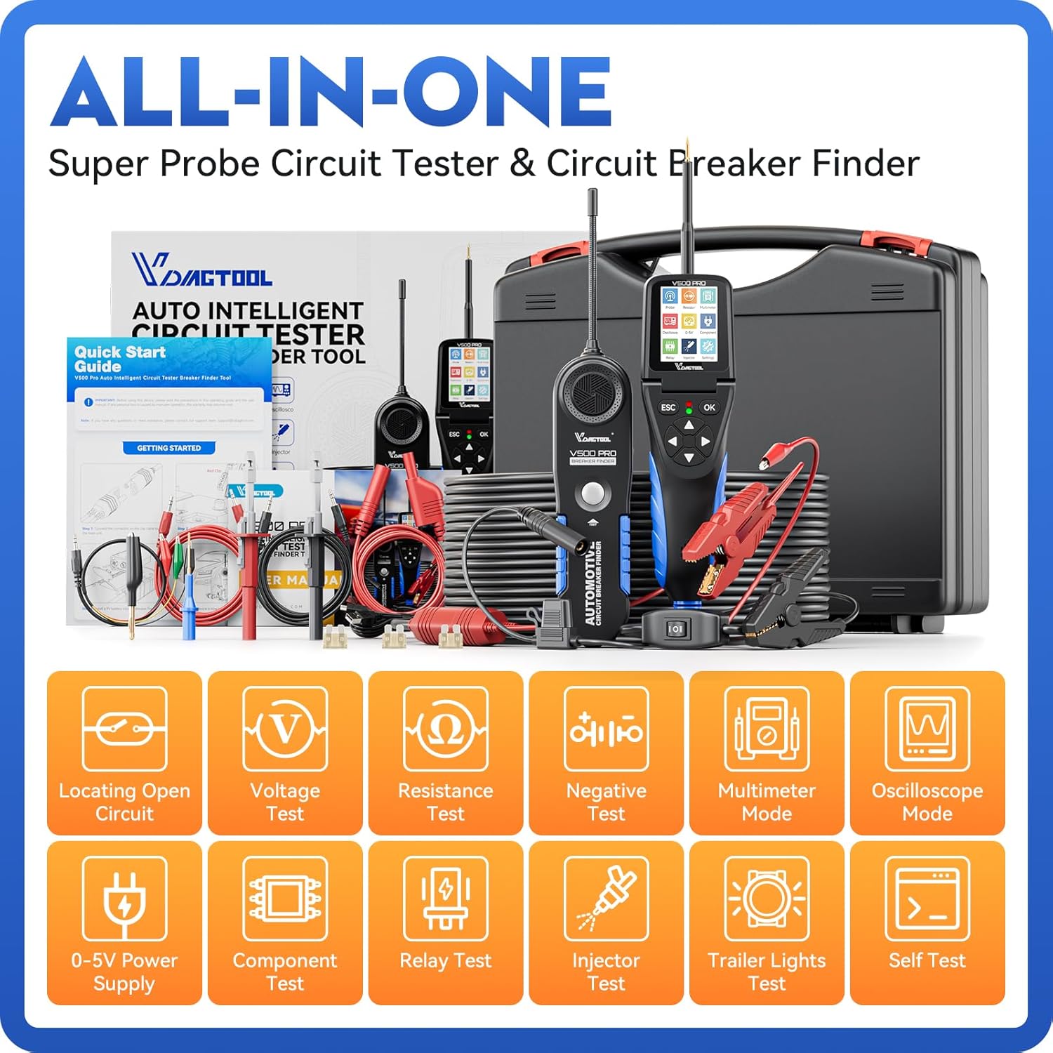
At this tier, some instruments incorporate oscilloscope or waveform-capture modes alongside their power delivery functions. For injector circuit diagnosis, the difference between confirming resistance and watching the actual injector waveform — the opening spike, hold current, and collapse — is the difference between ruling out an electrical fault and identifying exactly where in the firing sequence the failure occurs. That level of detail previously required a dedicated scope or a shop-grade scan tool.
Electronic Design’s automotive diagnostics coverage identifies waveform capture on injector and solenoid circuits as one of the highest-value capabilities a technician can add without moving to a full oscilloscope platform. For shops doing regular injector, ABS, and transmission solenoid work, the premium tier instruments pay for themselves quickly.
On the 24V question: both the Power Probe III and the Autel PowerScan PS100 are documented as working correctly on 24V diesel and fleet vehicle systems. Always confirm the rated voltage range on the specific model’s specification sheet before connecting to any system outside the standard 12V passenger-car norm — manufacturer spec sheets are the authoritative source, not third-party summaries.
VDIAGTOOL
$169.99
In stock on Amazon
Check price on AmazonTool Capability at a Glance
| Task | Standard DMM | Graphing DMM | Power Probe |
|---|---|---|---|
| Check injector coil resistance | ✓ | ✓ | ✓ |
| Fire injector / relay directly | ✗ | ✗ | ✓ |
| Graph parasitic drain over time | ✗ | ✓ | ✗ |
| Voltage drop on ground circuit | ✓ | ✓ | ✓ |
| Waveform / oscilloscope capture | ✗ | Some models | Some models |
Frequently Asked Questions
Can I test a fuel injector or solenoid with a regular multimeter, or do I need a power probe?
A DMM can confirm whether an injector’s coil is electrically intact via resistance test, and whether voltage is reaching the harness connector. It cannot command the injector to actually open. For functional testing — confirming the injector fires, sprays, and clicks — you need either a power probe to apply voltage directly or a noid light kit to confirm the ECU is sending a pulse signal. Both tools answer different questions; both are useful.
What is back-probing and why should I not just pierce the wire with a test lead?
Back-probing means inserting a test pin into the back of a connector alongside the terminal to make electrical contact without damaging the insulation. Piercing the wire leaves a hole that admits moisture and accelerates corrosion, creating future intermittent faults. On CAN bus signal wires, even minor corrosion changes resistance enough to cause communication errors months after the original test. As Electronic Design’s automotive diagnostics material notes, pierced test points are a disproportionate source of hard-to-trace intermittent codes. Back-probe pin kits exist specifically to avoid this failure mode.
How do I test for parasitic battery drain using a multimeter graph mode?
Connect your DMM in series with the negative battery terminal (meter set to amps or milliamps), then select graph or data-log mode if available. Let the vehicle sit with doors closed and key out. Watch the current trace — it should step down as modules sleep, arriving at a normal key-off draw of roughly 25–50 mA within a few minutes. Any module that wakes up and draws current intermittently appears as a spike on the graph, giving you a timing signature to track down.
What voltage drop reading across a ground connection indicates a problem?
ECM Web’s automotive ground circuit guidance puts the threshold at 100 mV (0.1 V) under load. Below 50 mV is clean. Above 100 mV warrants cleaning or replacing the connection. Above 300 mV you typically see hard electrical faults rather than intermittents.
Is a budget automotive circuit probe actually comparable to a Power Probe III?
On basic function — applying battery positive or negative to a test point — yes. On build quality, wire gauge, sustained-load capability, and long-term reliability in a professional shop environment, no. For occasional DIY use, budget probes perform the task adequately. For daily shop use, the Power Probe III’s heavier wire and connector quality justify the price difference.
The decision rule:
- If you’re diagnosing whether power reaches a component, a standard DMM is sufficient.
- If you need to command a component to operate independent of the vehicle’s control system, you need a power probe.
- If you’re hunting parasitic drain over time, a graphing DMM is the right tool.
- If you’re doing serious automotive diagnostics regularly, you need all three categories — they complement rather than replace each other.